GE Healthcare Surgical Navigation Tools
Improving accuracy of sensors to enable minimally-invasive surgeries
Context
- When
- 2009
- My Role
- Engineer
Surgeries are challenging to perform, even with image guidance. Bulky camera attachments also mean that surgeons need larger incisions to get started. At GE Healthcare, we found a way to enable minimally-invasive cranial, ENT, and spinal surgeries. Using electromagnetic sensors rather than cameras, we could direct surgeons to the precise location they were trying to operate on and help preserve vital tissue. You can think of our system as "surgical GPS".
However, the accuracy of the system was limited and worsened as surgical tools moved further from the operating table. I was asked to investigate this accuracy issue. By the end of this project, we improved the accuracy of our sensors 10x.
Characterizing the accuracy issue
Some quick background – our system used electromagnetic sensors at the tips of surgical tools. After imaging patients (e.g., using CT or MRI), surgeons could see the real-time position of their tools while operating inside a patient.
In building a smaller version of our sensor system, we ran into accuracy problems. We named it the "cup effect".

As you move a surgical tool (receiver) in a parallel plane to the surgical bed (transmitter), you should see a flat plane. However, we saw that as you moved the tool farther from the surgical bed, the flat plane started looking like a cup.
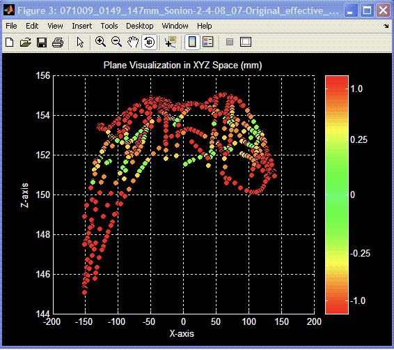
I wrote a MATLAB program to visualize the error and found the maximum error was 10 mm. To create a viable system, we needed to reduce the maximum error to less than 1 mm.

Creating an efficient testing method
The way we collected and analyzed this data was elegant, but inefficient. In order to have a faster feedback loop, I tried to automate as many steps in our testing procedure.

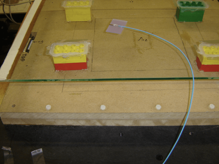
The test, called the "scribble test", had us scribble the receiver (what would be inside a surgical tool) like a pen across the surface of a glass plate.

To change the distance between the glass plate and the transmitter, we'd change the number of Legos between them. Then, we could collect more data by scribbling the receiver again.
I automated the analysis of each round of scribble testing. A JAVA program listened for new test data as you collected it.

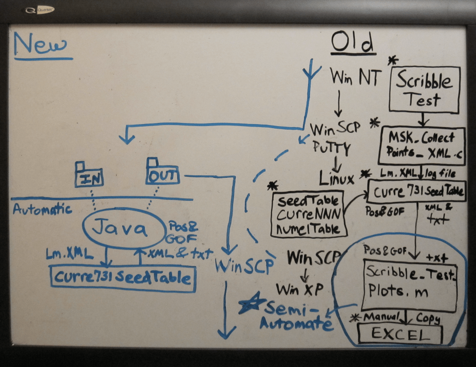
I then improved the MATLAB program to analyze a series of tests collected at various distances.
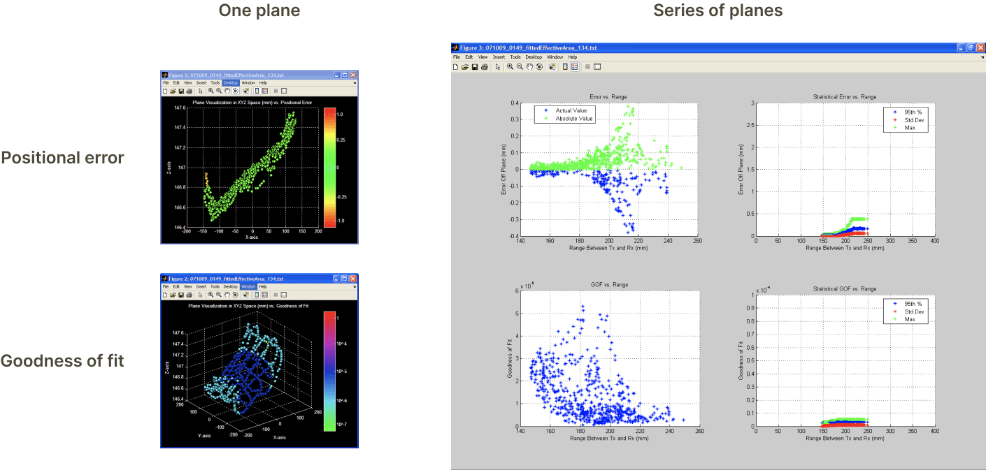
Now you could run a series of scribble tests and have the results before you walked back to your desk. This allowed our team to change our positioning models and rapidly see the results.
Improving the positioning model
For the previous, larger sensor system, we made assumptions to speed up the position calculations. However, those assumptions were no longer valid given the much smaller size of our new sensors.
With the help of a physicist on our team, I adjusted the positioning model and changed parameters to reduce the cup effect.
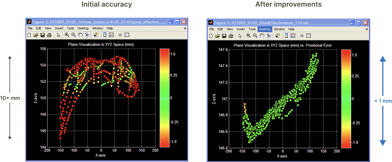
This process led to a 10x accuracy improvement and we reached our goal of having less than 1 mm error in the scribble test.
What I learned
In looking back at this project, I boiled down our success to creating a faster feedback loop of:
- running tests,
- discussing the error with our team,
- and iteratively changing the positioning model
As a result, surgeons could be more confident using our navigation tools to perform minimally-invasive surgeries.